The spring meeting of ASTM F16 took place the first week of May in San Antonio, Texas. F16 meets to review, update and propose new fastener standards. The meetings take place over several days, as F16 is comprised of eleven (11) Subcommittees, plus the main F16 Committee. The Main Committee meeting wraps up the Subcommittee meetings, as each chair reports on the respective meeting activities. Glenn Snowberger, as a member of F16, was in attendance representing Valley Forge.
As usual much work was accomplished in reviewing and voting on ballot issues pertaining to revising and or eliminating standards.
All changes, revisions or new proposed standards are balloted to the voting committee members. All negative ballots are discussed and voted on before any change can be initiated or any standard can be moved forward and submitted for a Main Ballot vote.
The subject of Hydrogen Embrittlement was a major point of discussion during several of the meetings. As a result of several fastener failures in the Gulf of Mexico, that were initially attributed to Hydrogen Embrittlement and then reversed, it was discovered that there are two (2) existing standards within ASTM covering Zinc Electroplating Plating that are not in agreement on the issue of at what hardness should fasteners be baked after plating. The standards are F1941 and B633, which are under the jurisdiction of two (2) separate committees, F16 Fasteners and B08 Metallic & Inorganic Coatings.
This difference is of major importance and cannot be left to exist. API ( American Petroleum Institute) and ASTM A01 have joined together in a request to have the two (2) committees find a common ground and resolved this disparity. It must be noted that B633 was changed in 2007 to require baking at hardness of RC 32 and above. Prior to 2007 it was in agreement with F1941. There are questions as to what brought about this change and what supporting studies and testing are available to support this change by B08.
VF Technical Article by President, Ron Clarke
 Assembly Description
A bracket retrofitted to a rail-car axle. The assembly consisted of four bolted bracket mounts retrofitted to the axle and the bracket then fastened to the mounts. The whole assembly used a quantity of twelve 3/4” and 5/8” Maxbolt, load indicating fasteners.
Field Tests
Field tests were performed by OEM on the Maxbolt load indicating fasteners by gathering data from two brackets bolted onto a right and left, car axle. All twenty four Maxbolt load readings, against rail-car miles traveled during a nine week period.
Results
Summary:
Month 1
After the first month and 1350 miles later, 9 out of 12 Maxbolts ~ 40% of the total fasteners, retained their initial preload of 75%
1 (one) Maxbolt: ~ 4% of the total, was down to 70% from initial 75% preload.
5 (five) Maxbolts: ~ 20% of the total, showed a load loss down to 65%
4 (four) Maxbolts: ~16% of the total, were down to a load of 60%
5 (five) Maxbolts: ~ 20% — were down to a low of 50%.
The fifteen bolts that had lost load were then all tightened back to 75%.
Month 2
After the second month, and an additional 2557 miles later, 22 out of 24 Maxbolts ~ 92% of the total fasteners, showed no load loss with readings unchanged at 75%.
Only 2 (two) maxbolts: ~ 8%, were down slightly with readings of 70%.
At this stage the two bolts were tightened back to 75% and the car run for a further 2860 miles when another load check was conducted.
This check showed 23 out of 24 Maxbolts ~ 96%, holding load at 75%. With one bolt down at 50%.
Conclusion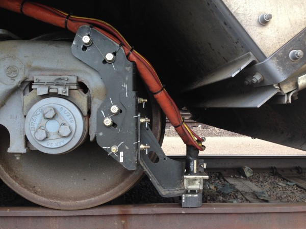
Specifically with this OEM’s railroad bolting assemblies, safety is a first consideration. For this application, Valley Forge’s Load Indicator Technology not only assures this safety with an accurate and instantly readable assembly preload, but also ensures quick maintenance, with no further need for routine re-torquing, other than those individual bolts reading low on the Maxbolt dial. Load indicating bolts are not for all applications but their ability to read accurate bolt load at a glance or during tightening, makes it ideal for this critical bolted assembly. The quantitative clamp load readings displayed for this test, would have been by any other method, difficult and extremely expensive, if not impossible to obtain, without the Valley Forge Maxbolt™ Load Indicating System.
by Rusty Flocken, Mechanical Engineer
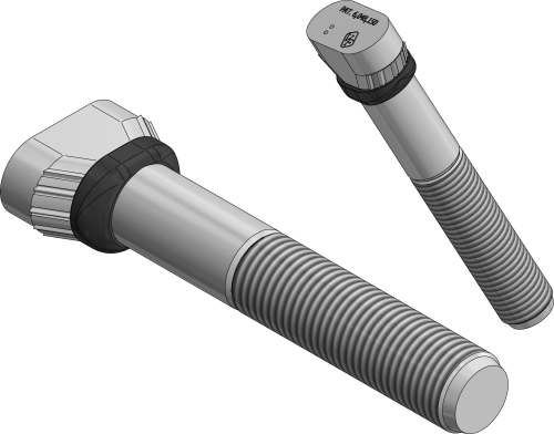 Valley Forge has recently developed a liner bolt innovation to improve the reliability of mill liners and liner bolts in ore grinding mill applications. Recently, concern has been raised about liner breakages triggered by stress concentrations found at the base of the liner pocket where contact is typically made with the bolt head. Liner bolt customers have also reported problems of ‘racing’ due to leakage of slurry between liner pocket and bolt head. This phenomenon can cause wear and premature failure to bolts and the mill shell alike.
The Sealing Mill™ Ridgeback® liner bolt has been designed and evaluated to prevent problems related to load distribution, as well as slurry leakage, which can lead to ‘racing’. The Sealing Mill™ Ridgeback® produces effective sealing of the bolt to liner pocket throughout the full range of bolt capacity, including very low loading conditions. Additionally, the polymer bushing is designed to transfer a pre-determined amount of bolt load while remaining load is distributed higher up on the head.
The polymer bushing was selected with a durometer rating based on results from testing. In order to achieve the best balance of load distribution and part life, factors such as memory retention, compliance and load bearing capacity were all considered.
The sealing mill liner bolt is currently available.
by Rusty Flocken, Mechanical Engineer
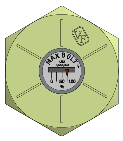
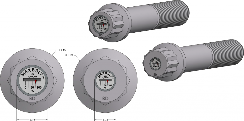
For over a decade, Valley Forge has offered Maxbolt™ load indicating fasteners to customers requiring direct load indication. Now the same technology can be installed in fasteners which were previously too small to accommodate a Maxbolt™ indicator. The Miniature Maxbolt™ was originally developed for a customer requiring fitment into a 5/8” diameter hex cap screw for mounting on a rail-car. For the first time ever, this customer has been able to record and catalog actual bolt loads over time using a spreadsheet. This information can be used to highlight special characteristics such as a bolt’s behavior as a function of its position within an assembly, or maintenance activities which may change bolt loads. The information can also be used, in general, to categorize overall behaviors of the joint such as embedment. This phenomenon and others occur on an average over the sum of all bolts in the joint, and can greatly affect joint performance over time.
The Miniature Maxbolt is set apart from previous Maxbolt™ designs in that the primary goal was to create the most compact indicator possible in order to reduce the impact of material removal on small bolts. This is our only Maxbolt™ designed to use a smaller 0.1875 diameter gage pin, allowing for less reduction in cross-sectional area. The Miniature Maxbolt™ can be installed into bolts as small as 5/8” [M16], installations can also be made in 3/4” [M20] bolts, with the added benefit of less de-ration when compared to a standard Maxbolt™. Both sizes of bolts will require an increased head height to accommodate the Maxbolt™ indicator.
 When it was suggested that I pinch hit for Ron as the Guest Anecdote writer I was immediately struck with fear. I felt like a new stand-up comedian making his first appearance at a comedy club. I was waiting to take the mic following someone like Jerry Seinfeld: “A tough act to follow’’.

